- Markets
- Products
- Services
- Newsroom
- People & Careers
- About Nexans
- Tools & Resources
- Search
- Contact us
- Compare
- Sign in
Mechanical Connectors up to 52 kV (M-Series)

Mechanical Connectors up to 52 kV (M-Series)
Mechanical Connectors up to 52 kV with shear-off-head bolts and transverse grooving (M-Series)
Read moreDescription
Description
Standards
-
TestIEC 61238-1
Describtion
M-Series mechanical connectors are assembled with multiple shear-off-head bolts and are therefore a reliable and economical way of connecting identical or different conductor cross-sections and conductor materials.
Material:
Connector Body:
high strength aluminum alloy
Bolts:
brass, tin-plated, with inner and outer hexagon or aluminum alloy
Surface:
Connector Body:
tin-plated
Centering:
center rings or inserts are enclosed for centric conductor positioning
Connectors filled with compound and sealed in plastic.
Advantages
Simple, quick installation:
With common commercially available inner and outer hexagon tools or an approved impact wrench.
Minimum storage costs:
The cross-sectional area from 16 mm² to 1200 mm² is covered by just 4 types of connectors.
Universal applicability:
Can be used for copper and aluminium conductors according to EN 60228 classes 1 & 2. For use of our mechanical connectors with class 5 flexible copper conductors, please contact us.
Proven quality:
Tested for class 2 conductors according to IEC 61238-1, in failure-free operation for more than 20 years.
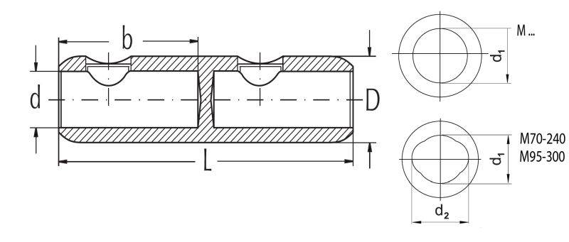
Dimensions M-Series
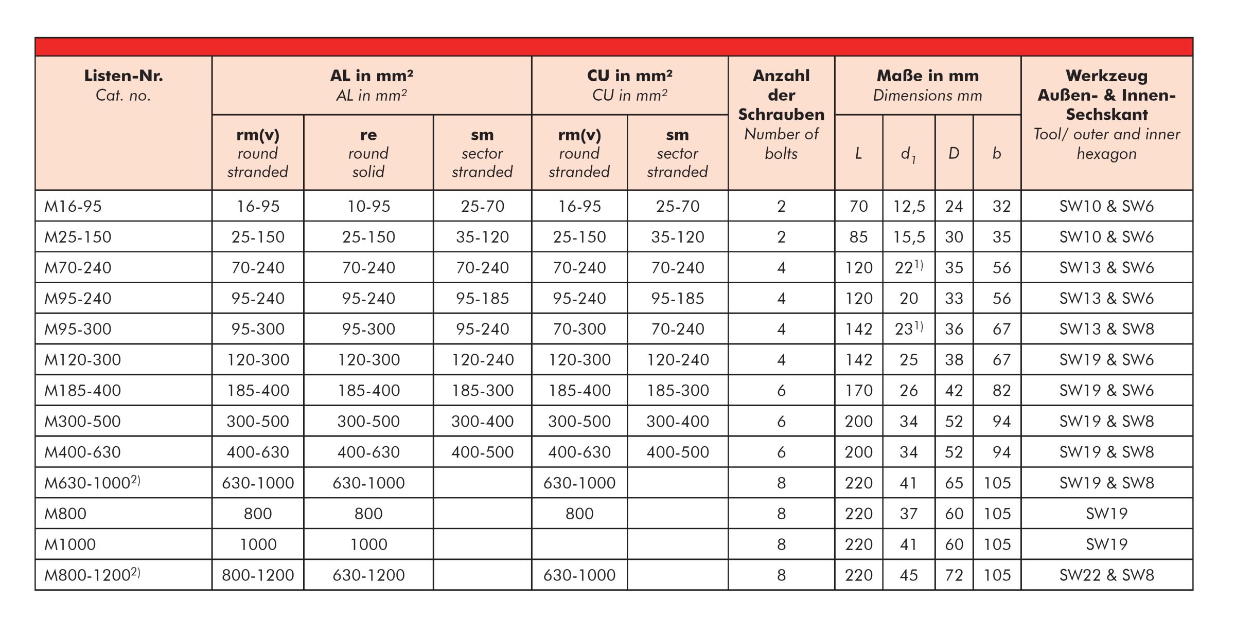
Selection table M-Series
Technical note M-Series
(1) Dimension d2 =26 mm
(2) Centric conductor positioning by center inserts
Technical details
The bolt has an inner and outer hexagon. Both are related to the various shear-off-areas of the bolt and their different torque moments.
The torque moments follow the rule that large conductor cross sections need high torque moments and smaller cross sections need lower torque moments.
The installation instruction describes the use of both hexagons and of the various center rings and inserts, for the respective conductor types.
Centring of the conductor
For the centric position of smaller conductor cross- sections in the conductor channel, we use centring rings that must be pressed all the way into the channel of the connector before assembling the corresponding conductor cross-section. The centring rings differ in colour and are assigned to the respective type of conductor. Appropriate assembly instructions describe which type of conductor the centring rings are to be used for. The conductor is centred using a centring insert in the case of the largest cross-sectional area.
Pictograms
Technical instructions and application information (mechanical connectors and cable lugs)
The data given were determined diligently, but do not release our customers of the duty to carry out tests themselves in order to check the suitability of the products delivered by us for the intended use. We reserve the right to modify characteristic and performance data according to the present state of technology. Processing and use of the products cannot be controlled by us and are therefore exclusively in your field of responsibility.
Our products meet the VDE standards respectively correspond to DIN pages and IEC recommendations. Attention: Before first design in please contact manufacturer.
The products, described in this catalogue, are designed for connection of energy cable conductors (Class 1 & 2) with description of round solid (RE), round stranded (RM), as well as sector solid (SE), sector stranded (SM) and round stranded compacted (RMV) exclusively on
bare conductors and for conductor temperatures up to 90 °C. All conductor filling materials like tapes, yarn, powder or similar need to be completely removed before mounting.
The conductor standard DIN EN 60228 does not define binding cable dimensions. Despite of all carefulness of the manufacturer, general application capability of GPH® compression products for EN conductors cannot be assured. A check on basis of the actual existing conductor dimensions by the user is indispensable. This applies also for the application of flexible conductors (Class 5 & 6).
For the use of flexible copper conductors (Class 5) with the M/C series, an additional bolt set WS … CU-FLEX has to be used. By using the D series, cross-sections given in the selection table can be clamped with or without contact sleeve. A check on basis of the actual existing conductor dimensions by the user is indispensable. This applies also for the application of Class 6 conductors or other special conductors.
Impact wrenches have to be approved by Nexans! Depending on different conductor material or conductor type, indicated values may differ from test values acc. to IEC 61238-1. The use of fine stranded conductors has to be approved by Nexans Power Accessories Germany GmbH.
Our responsibilities are only those listed in the latest edition of “General terms and conditions for the supply of products and services of the electrical and electronics industry”. We only use packaging materials able to be recycled due to the latest regulation on packaging. Sales packaging are not taken back.
Reprinting, even partial, only with special allowance. We reserve the right to alter or modify the characteristics described. Illustrations and drawings may only show a close reflection and are not decisive. Weights are approximate values including the carton package. This catalogue substitutes all former editions. Types or versions not part of this catalogue are available on request.
Hof, May 2021
Resources
Resources
Our websites
Select your country to find our products and solutions
-
Africa
- Africa
- Ghana
- Ivory Coast
- Morocco
- North West Africa
- Americas
- Asia
- Europe
- Oceania


